This guide was written for one specific job: a 2002 Harley-Davidson Softail with the Twin Cam 88B engine and 5-speed transmission, a drain plug seized solid in the bottom of the bike between the frame rails, and two men who would rather pull the whole powertrain than pay a shop. It walks the job in the order you will actually do it: identify the plugs, try to free the stuck one while the bike is still together, then — win or lose — take the engine out, take the transmission out, finish the plug fight on the bench where you have room to work, repair the threads properly, and put it all back together with the right torque on every fastener.
Everything in here is written in plain garage language, with the Softail-specific details called out where this bike differs from other Harleys. Read each section all the way through before you pick up a wrench for that section. Keep a phone camera in your pocket: photograph every connector, hose, and bolt pattern before you take it apart. Future-you, standing there in three weeks holding a mystery bracket, will be grateful.
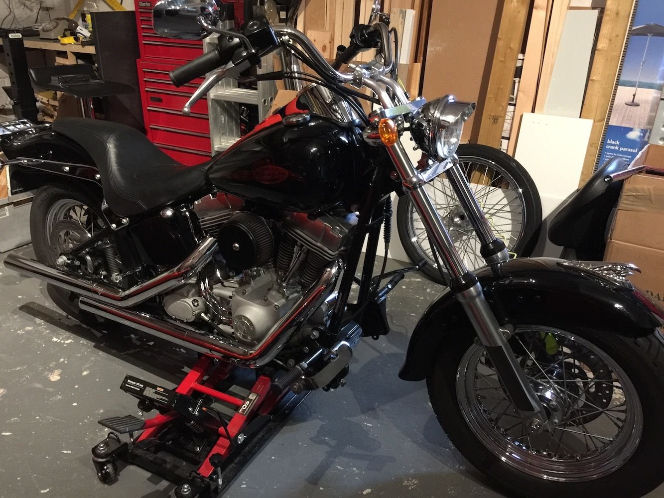
Figure 1. A Softail in the garage, sitting on a scissor-style motorcycle jack. This is the working position for almost everything in this guide: bike upright, both wheels just clear or lightly loaded, and the machine strapped so it cannot tip while you lean on a breaker bar.
Non-negotiable safety rules
Support. Never work under or beside a bike that is held up by a jack alone. Get it on a lift table or a proper motorcycle jack, strap it down with soft ties, and block it so a hard pull on a breaker bar cannot walk it off. The engine weighs roughly 150 lb and the transmission about 60 lb — plan every lift before you make it.
Battery. Disconnect the battery before any mechanical or electrical work, negative cable first, and tape the terminal so it cannot spring back onto the post. A shorted positive cable against the frame can burn the bike — and you.
Fuel and fire. Drain the tank or remove it before teardown. No smoking, no open flame, no grinding sparks near fuel or fuel-soaked rags. Keep a charged fire extinguisher within arm's reach any time a torch comes out — that is not decoration, it is part of the seized-plug procedure.
Hot oil. Warm oil drains better and burns skin just fine. Gloves and patience.
Two people. Engine and transmission lifts are two-person lifts, or one person with a hoist and a sling. No exceptions, no hero moves.
Eye protection for drilling, grinding, hammering on extractors, and anything involving a torch, compressed air, or penetrating oil under pressure.
⚠ THE ONE WARNING THAT MATTERS MOST: There is a plug in the bottom of the engine crankcase that is NOT a drain plug. It is a factory plug in an oil passage, left over from machining the cases. It will come out if you force it, almost nothing will drain, and getting it to seal again can turn into a leaking, thread-damaged nightmare. Section 2 shows you exactly which plug is which. Read it before you touch anything underneath this motorcycle.
How the job flows
Identify the plugs and confirm which motor you have (Sections 1–2).
Attack the seized plug in the bike, least aggressive method first (Section 3). If it comes out, drain everything and carry on — the teardown below is the same either way.
Strip and remove the engine (Section 5).
Remove the transmission (Section 6) — on a Softail this means the swingarm pivot comes out too, because the pivot shaft runs through the transmission case.
Finish the plug on the bench, repair threads if needed, and reassemble (Section 7).
Refill, adjust, and first-start checks (Section 8).
SECTION 1 Confirm Which Motor You Have
The bike is described two ways in the family: "1340" and "88 cubic inch." Those are two different engines, and they are not interchangeable when you are hunting for drain plugs and torque specs, so settle it before anything else. Here is the short version: a factory-built 2002 Softail left Milwaukee with a Twin Cam 88B — 88 cubic inches, roughly 1450 cc, with a pair of chain-driven balance shafts inside the cases (that is what the "B" stands for) so the motor could be bolted solidly into the Softail frame without shaking the rider apart. The 1340 cc engine is the Evolution ("Evo"), 80 cubic inches, and Harley stopped putting it in Softails after the 1999 model year. If this bike is a genuine 2002 with its original motor, it is a Twin Cam 88B, and this guide is written for it. If somebody swapped in an Evo or an aftermarket motor somewhere in the last 24 years, the five-minute check below will tell you.
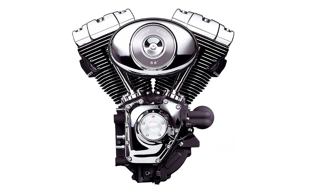
Figure 2. A Twin Cam 88, front view. Learn this silhouette: deep, closely stacked cooling fins, a big round cam cover low on the right side of the cases, and pushrod tubes that run nearly parallel to the cylinders. The factory air-cleaner insert on most of these simply reads "Twin Cam 88."
The five-minute identification check
Check
Twin Cam 88B (2000–2006 Softail)
Evolution 1340 (1984–1999 Softail)
Model year / VIN
2000 or later Softail. 10th VIN character for 2002 is "2."
1999 or earlier Softail.
Cam cover (right side, low)
Large, round cover held by five bolts, roughly the size of a salad plate.
Smaller, more oval "nose cone" cover.
Rocker boxes
Three-piece boxes with a distinct stepped profile; the covers look layered.
Two-piece boxes, squared-off and slab-sided — the reason Evos got nicknamed "Blockheads."
Engine/transmission joint
Transmission case bolts directly and flatly against the back of the engine cases; the two read as one long powertrain unit.
Transmission sits offset from the motor with a visible gap and its own separate mounting arrangement.
Engine oil drain
Plug in the frame crossmember below/behind the transmission (Section 2).
Drain hose at the front of the transmission, left side, with a plug in the end of the hose.
Air cleaner insert
Commonly stamped "Twin Cam 88."
Commonly stamped "Evolution."
IF YOURS TURNS OUT TO BE AN EVO: Do not throw this guide away — the seized-plug playbook, the primary strip, and the general teardown order are the same. The differences that matter: the Evo's engine oil drains from a rubber hose on the left side in front of the transmission, not from a plug under the bike; the Evo transmission drain is in the bottom of the transmission case much like the Twin Cam's; Evo engine and transmission come apart and come out with more daylight between them; and Evo torque values differ on several fasteners, so work from an Evo manual for specs. Everything from Section 3 onward is written for the Twin Cam, which is what a 2002 carries.
SECTION 2 The Plug Map — Which Plug Is Which
A Harley Big Twin carries three separate oils — engine oil, transmission oil, and primary chaincase oil — and each one has its own drain. Under a Softail there are also a couple of plugs and set screws that are not drains at all. This is where expensive mistakes happen, so go slowly. Warm the bike up for a few minutes before any drain: warm oil flows, and warm cases also give a seized plug its best chance of moving (Section 3).
Here is the map. On this bike, the engine oil lives in a separate tank under the seat (a "dry sump" system — the tank holds the oil, the pump circulates it). The transmission sits behind the engine with its own oil pan formed in the bottom of the case, right between the two hidden rear shocks. The primary chaincase is the big cover on the left side of the bike. The plug that matches our problem — low in the middle of the bike, wedged between the frame rails, rust on it, hex starting to round — is one of the first two below, and most often the transmission drain.
Figure 3. Original schematic of the underside of a Twin Cam Softail. Green plugs are drains. The red X is the crankcase plug that must never come out. Primary drain (not visible in this view) is on the bottom rear edge of the primary case, left side of the bike.
The three real drains
Plug
Where it is
What fits it
Sealing
Engine oil drain
Follow the large hose from the bottom rear of the oil tank (under the seat) down behind the transmission. It stubs into a boss on the frame crossmember below/behind the transmission. The plug screws into the underside of that boss, pointing straight down, just below the swingarm pivot area on the right side. This drains the oil tank — which is where engine oil lives.
5/8 in hex, with a 1/4 in Allen socket in the center (either drive works)
Straight thread, seals on a rubber O-ring. No tape, no sealant.
Transmission drain
Dead center in the lowest point of the transmission case, pointing straight down, sitting between the two hidden rear shocks and right above the frame crossmember. This is the tight, awkward, rust-collecting one — the plug this whole project is about. A mirror and a flashlight from below will show it clearly.
5/8 in hex with 1/4 in Allen center
Straight thread, O-ring seal. No tape, no sealant.
Primary chaincase drain
Bottom rear edge of the primary case on the left side, underneath the round clutch (derby) cover area. Points down/back at a slight angle.
T-40 Torx
Tapered pipe thread — a small amount of thread sealant is acceptable here, and only here. Snug it; these threads strip easily.
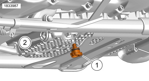
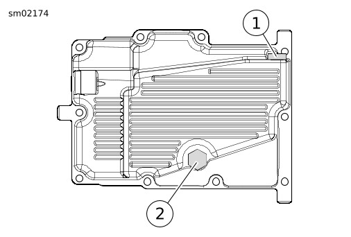
Figure 4. Factory-style underside view of a bottom drain plug (1) sitting in its pan, up between frame structure — exactly the "no room to swing a wrench" situation on this bike. Note how the plug points straight down and the only access is from directly below.Figure 5. Bottom pan, line drawing. The drain is the hex plug at (2): a plain 5/8 in hex with a 1/4 in Allen recess in the middle, sealing on an O-ring. If the hex is what is rounding off on your plug, the Allen recess in the center is your second chance — Section 3 uses it.
⚠ NEVER REMOVE — CRANKCASE PLUG: On the underside of the engine cases themselves there is a flat Allen-head plug sitting in the crankcase sump area. It is an oil-gallery plug installed at the factory after the cases were machined. It is not a service drain. If you take it out you will get a few spoonfuls of sump oil, a false sense of accomplishment, and — if the threads or the plug's seal are disturbed — a weep that is miserable to fix. Same rule for any set-screw-looking plug in the engine or transmission cases: if it isn't one of the three drains in the table above, it stays in. If you have already taken the crankcase plug out by mistake, thread it back in with a little thread sealant on the threads, snug it down, and leave it alone forever.
WHICH ONE IS STUCK ON THIS BIKE? Get under the bike with a mirror. If the stuck plug is in a boss that is part of the frame crossmember (with a big rubber hose coming into the top of the boss), it is the engine oil drain. If it is in the bottom of the transmission case, between the shocks, it is the transmission drain. Both are removed and repaired exactly the same way, and both get dramatically easier with the powertrain on the bench. Either way, this guide has you covered.
Capacities, for later: engine oil about 3 quarts with a filter change (add 2.5, run it, then top up checking the tank dipstick with the bike on its sidestand). Transmission: 20–24 ounces. Primary: 32 ounces (1 quart), filled through the derby cover opening to the bottom edge of the clutch diaphragm spring.
SECTION 3 The Seized-Plug Playbook
Here is the situation in plain terms: a steel plug, in an aluminum case (or a steel frame boss), that has probably not moved in years, in the worst access spot on the motorcycle, with rust on the threads and a hex head that is starting to round. The good news is that this is a solved problem. The trick is discipline: work the ladder below from the top, one rung at a time, and stop the moment a rung starts damaging the plug. Every rung you skip makes the next owner's job harder, and right now the next owner is you, on a bench, in Section 7 — where almost all of these rungs get easier anyway.
Two things before rung one. First, direction: lying on your back looking up at a plug that points down, "counterclockwise" is judged from your viewpoint looking at the plug face — lefty-loosey as you see it. More than one plug has been tightened to death by a man turning it the wrong way from underneath. Second, clean first: wire-brush the plug head and the area around it, and blow the grit out of the Allen recess. Half of "seized" plugs are actually "socket wasn't fully seated" plugs.
RUNG 1 The right socket, seated hard
Run the engine for two or three minutes so the cases are warm to the touch, then shut it off. Warm aluminum expands slightly more than the steel plug and breaks the corrosion's grip.
Use a six-point 5/8 in socket — never a twelve-point, never an open-end wrench. Six-point sockets grip the flats; twelve-points grip the corners, which is how hexes get rounded in the first place.
Seat the socket fully. If rust or grime keeps it from sitting flat on the plug's flange, tap it on with a hammer until it does.
Put a breaker bar on it and give it a firm, sharp jolt rather than a slow, growing pull. Static friction breaks with shock, not with creep.
If the hex already feels soft, switch to the plug's other drive: a 1/4 in Allen (hex) socket, tapped fully into the center recess, same breaker-bar treatment.
RUNG 2 Penetrating oil and shock
Soak the plug threads with a real penetrating oil (PB B'laster, Kroil, or similar — standard WD-40 is a water displacer, not a true penetrant). Spray from below so it runs into the thread joint.
Wait at least 20 minutes. Overnight is better. Re-apply two or three times during the soak.
Before each attempt, strike the face of the plug squarely a few times with a hammer and a flat punch. The shock cracks the rust bond between the threads and vibrates penetrant deeper in.
Retry Rung 1 after every soak-and-shock cycle. Most "impossible" plugs surrender to patience somewhere in this rung.
RUNG 3 Heat the case, freeze the plug
Extinguisher in reach, fuel tank area clear, no fuel or oil leaks dripping anywhere near. Drain what oil you can first if any drain will open.
Heat the case (or frame boss) around the plug with a heat gun, or a propane torch kept moving — you are warming the aluminum so it grows away from the plug, not cooking the plug itself. A couple of minutes to "too hot to hold a bare hand on" is the target zone for a heat gun.
Immediately blast the plug itself with freeze spray (or an upside-down can of electronics duster) for 10–15 seconds to shrink it in its hole.
Socket on, breaker bar, sharp jolt — while the temperature difference lasts. You have about thirty seconds of advantage; have everything staged before you start heating.
RUNG 4 Manual impact driver
Fit a hand impact driver (the kind you hit with a hammer) with either the 5/8 in six-point socket or the 1/4 in Allen bit, whichever drive on the plug is healthier. Confirm the driver is set to loosen.
Seat it, hold firm inward pressure and a twist toward loosen, and strike the driver hard and square.
Two or three solid hits convert hammer shock directly into turning force without twisting the head off — this tool exists for exactly this plug.
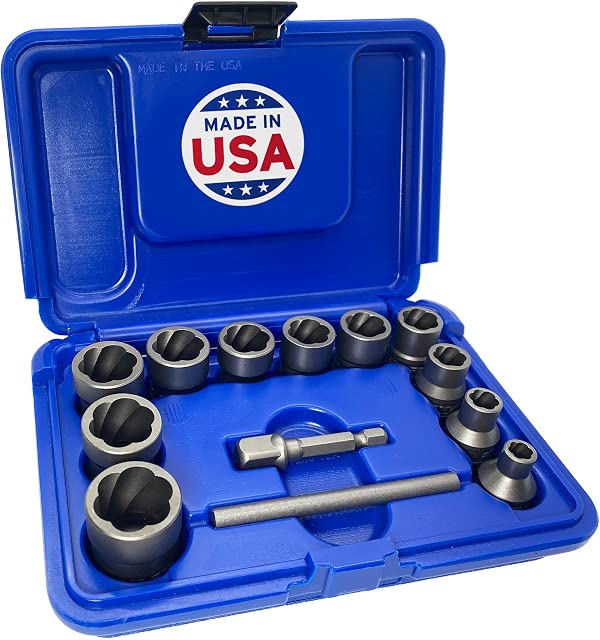
Figure 6. A bolt-extractor ("turbo socket") set. The spiral flutes inside each socket bite into a rounded hex as you turn counterclockwise, gripping harder the more force you apply. Rung 5 lives in this box.
RUNG 5 Extractor socket — for when the hex rounds
Pick the extractor socket that almost fits over the damaged hex. It should need to be hammered on — that interference is the grip.
Drive it fully onto the plug with a hammer until it bottoms out.
Turn it out with a breaker bar in one committed pull. The flutes dig in as torque rises.
Accept the trade: an extractor socket usually ruins the plug it removes. That is fine — a replacement magnetic drain plug costs less than a pizza, and you were never going to reuse a rusted, rounded plug anyway.
Supplement, if there's meat left on the head: a pair of quality locking pliers clamped on with everything you have can walk a plug out, and a sharp cold chisel tapped tangentially against the edge of the flange — driving it counterclockwise, one bite at a time — is the old-timer's version of the same idea. Both are hard to do well lying under a bike between frame rails. Which brings us to the honest stopping rule:
KNOW WHEN TO STOP IN THE BIKE: If the hex is rounding, the Allen recess is chewing out, and Rungs 1–5 haven't moved it, stop. You are one bad pull away from a headless plug in a case you still have to get out from under a motorcycle. You are pulling this powertrain anyway. On the bench (Section 7) you get perfect access, a drill press, and Rungs 6–8 below — which succeed essentially every time. The plug does not care whether it loses the fight under the bike or on the bench, but your knuckles and the transmission case do.
RUNG 6 Weld a nut on it (bench preferred)
Clean the plug face to bare metal. Pick a nut one size larger than the plug head and center it on the plug face.
Disconnect the battery if the case is still in the bike; ground the welder as close to the plug as you can.
Plug-weld the nut to the plug through the nut's center, filling it solidly.
Let it cool just to dark, then put a socket on your new, oversized, perfectly shaped "plug head" and turn it out. The weld heat has already broken the thread bond — this method very rarely fails.
RUNG 7 Left-hand drill bit, then screw extractor (last resort)
Center-punch the plug dead center. Use a drill press on the bench if at all possible — a wandering bit in a case is a catastrophe, a centered bit is a procedure.
Drill with a left-hand bit, drill in reverse, starting small (about 1/8 in). Coat the bit in heavy grease to trap chips. Frequently, the bit catches and simply unscrews the plug while drilling — job done.
If it doesn't walk out, step up one bit size, then fit a spiral screw extractor (EZ-Out type) into the hole and turn it counterclockwise with a tap wrench. Extractors are hardened and brittle: steady pressure, no side load, or they snap — and a snapped extractor is harder than any drill you own.
If the plug still won't come, drill it out progressively to just under the thread's minor diameter and pick the remaining thread shell out with a small punch. Tedious, but the threads underneath usually survive.
RUNG 8 If the threads are hurt
Removing the plug is only half the job if the hole is damaged. Section 7 covers the full repair menu — chasing the threads with a tap, a Time-Sert solid insert, or an oversize self-tapping replacement plug — and how to choose between them.
SECTION 4 Tools & Supplies Checklist
Check these off on paper before the first bolt turns. The starred items are the ones men usually discover they need at 9 p.m. with the primary already open.
Lifting & support
Motorcycle lift table or frame jack, rated for the bike
Two ratchet straps / soft ties
Scissor jack or small floor jack + wood blocks
Engine stand or stout bench + blocking
Engine hoist or come-along + lifting sling *
Hand tools
Six-point socket set, incl. 5/8 in *
Allen (hex) socket set, incl. 1/4 in *
Torx sockets, incl. T-40 *
18 in breaker bar
Torque wrench, ft-lb, to at least 175 ft-lb *
Torque wrench, in-lb
Combination wrenches, full set
Manual (hammer) impact driver *
Primary drive locking bar/tool *
Snap-ring pliers, picks, magnet
Feeler gauges; belt tension gauge
Seized-plug kit
Penetrating oil (PB B'laster / Kroil)
Bolt extractor (turbo socket) set *
Locking pliers; cold chisel; punches
Heat gun and/or propane torch
Freeze spray or inverted duster cans
Wire brushes
Left-hand drill bit set *
Screw extractor (EZ-Out) set
Welder access (MIG) for Rung 6
Fire extinguisher, charged, in reach
Thread repair & reassembly
Thread chaser / tap, 1/2-20 (plug thread)
Time-Sert kit 1/2-20 (if threads are hurt)
Oversize self-tapping drain plug (backup plan)
New magnetic drain plug(s) + O-ring kit
Loctite 243 (blue) and 262/271 (red)
Anti-seize compound
Thread sealant (primary plug only)
Gaskets: primary cover, derby, inspection, transmission side cover, exhaust port gaskets
Primary case O-ring / seals as needed
Fluids & consumables
Engine oil 20W-50, 3 qt + new oil filter
Transmission oil, 1 qt (20–24 oz used)
Primary fluid, 1 qt
Low-profile drain pans (must fit under the bike)
Brake cleaner, shop towels, nitrile gloves
Zip bags, paint marker, masking tape, tags
Cardboard for laying out parts in order
SECTION 5 Engine Removal, Step by Step
The Twin Cam in a Softail is solid-mounted: no rubber isolators, the cases bolt straight to the frame at the front and straight to the transmission at the back, and the transmission bolts to the frame. The inner primary case bridges engine and transmission on the left side, tying all three together. That architecture dictates the order below: fluids and electrics first, primary drive second (it is the bridge), then mounts, then the engine lifts up, tilts, and comes out the right side of the frame.
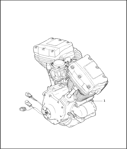
Figure 7. The complete Twin Cam engine as one assembly (factory parts-book style line drawing). This whole unit — roughly 150 lb with oil drained — is what comes out. Note the wiring pigtails at the lower left: everything electrical gets disconnected and labeled before the engine moves an inch.
Phase A — Set up and drain
Bike on the lift, upright, strapped. Front wheel chocked or clamped. Transmission in neutral.
Seat off. Disconnect the battery: negative cable first, then positive. Tape both terminals.
Warm the engine briefly if it still runs, then drain what you can: engine oil at the crossmember plug (if it will move), transmission oil at the case plug (if it will move), primary oil at the T-40 plug. On this bike, the seized plug may refuse — that's fine. Whatever won't drain now will drain on the bench; just be ready for the mess when cases open, and drain the primary through its plug or by cracking the cover over a pan.
Fuel: turn the petcock OFF (carbureted bikes) or relieve fuel pressure and use the quick-disconnect (EFI bikes). Remove the fuel tank — console/dash off, fuel line disconnected and plugged, vent and overflow hoses noted, two bolts, lift it clear and set it somewhere it cannot fall or get scratched.
Remove the exhaust system: flange nuts at both heads (penetrating oil first — these studs snap), muffler and bracket bolts, and lift the whole system away. Bag the flange nuts and note the port gaskets for replacement.
Remove the air cleaner and its backing plate. Disconnect the throttle and idle cables at the carburetor or throttle body (note which cable is which — photograph it), or unbolt the intake and leave the carb/throttle body wired and tied up out of the way. Cap the intake opening.
Floorboards or pegs, brake pedal, and anything else that crowds the right side of the engine: off or swung clear. Remove the horn and the front voltage regulator bolts if the wiring needs slack.
Phase B — Disconnect everything attached to the engine
Work this list top to bottom, tagging every connector and hose with tape as it comes apart. If it connects the engine to the frame, the tank, or the transmission's oil system, it comes off now.
Spark plug wires off the plugs; coil primary wires disconnected at the coil. Label front/rear.
Crank position sensor connector (front left of the cases, low).
Oil pressure switch wire (right side, near the cam cover/front of the cases).
Stator/regulator connector at the front of the cases — separate the plug and free the harness from its clips.
Starter cables: the heavy battery cable and the solenoid trigger wire at the starter (right rear of the engine, behind the oil tank). Note: battery is already disconnected — that's why.
Neutral switch wire (top of the transmission case, but do it now while you're here).
Oil lines at the oil tank and engine: feed, return, and vent hoses. Label each one — swapping feed and return on reassembly will ruin your whole month. Clamp hoses before pulling them to limit the spill, and cap the tank fittings. Also remove the oil tank's drain hose from the frame crossmember boss if it blocks your socket work.
Clutch cable: slacken the adjuster fully, then disconnect at the transmission side (release) cover per Section 6, Phase A — or free the cable from the lever and frame clips now and finish at the cover later. Route it clear of the primary.
Shift linkage rod: unbolt from the transmission shift lever and tie it out of the way. Mark the lever's spline position with a paint pen if you remove the lever itself.
Anything else your particular bike has added over 24 years — aftermarket oil coolers, extra grounds, alarm modules. Photograph, tag, disconnect.
Phase C — Strip the primary drive (the bridge)
Outer primary cover off: drain first (done in Phase A), then remove the cover bolts in a crisscross pattern, keeping track of bolt lengths — they are not all the same. Cover comes off with the gasket; the clutch inspection (derby) cover can stay on the outer cover if it's already off as one piece.
Inspect what you've got: engine compensator sprocket at the front, clutch basket at the rear, duplex chain between them, chain adjuster shoe at the bottom.
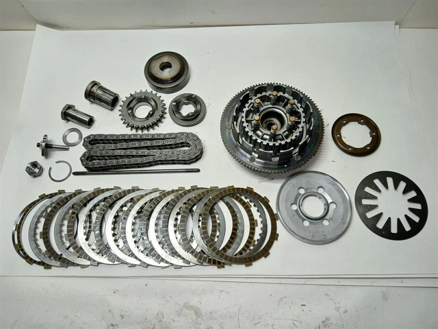
Figure 8. The complete primary drive from a 2002 Softail, laid out in order: compensator parts (upper left), chain, clutch basket with its ring gear (right), and the clutch plate pack fanned out below. Laid out like this, in removal order, reassembly is just this photograph run backwards.
Fit the primary locking tool (bar or block) between the chain and sprockets so the shafts cannot rotate. This is not optional improvisation — a screwdriver jammed in the chain will chip teeth.
Compensator nut (front sprocket, on the crankshaft): right-hand thread, red threadlocker from the factory, and tight. Breaker bar or impact gun; it comes off counterclockwise like a normal nut. Keep the compensator stack in order as it comes off — sprocket, sliding cam, spring pack/diaphragm washers — and note the order and orientation of every washer.
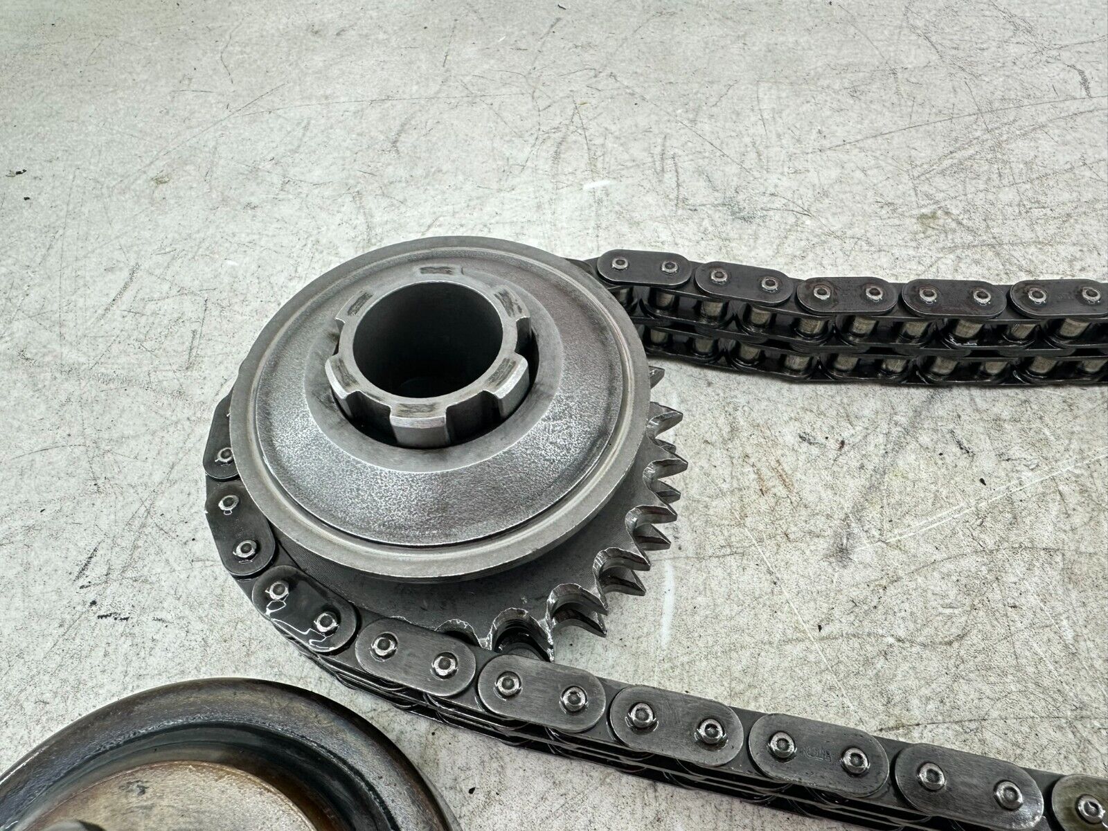
Figure 9. Compensator sprocket and duplex primary chain on the bench. The compensator is the engine's shock absorber: the sprocket drives through a ramped cam and spring pack, which is why its stack order matters and why its nut gets the biggest torque number on the motorcycle.
⚠ LEFT-HAND THREAD — CLUTCH HUB NUT: The nut holding the clutch hub to the transmission mainshaft is a LEFT-HAND thread. It tightens counterclockwise and loosens clockwise. It is also installed with red threadlocker. Turning it the "normal" way does not loosen it — it tightens it further, and men have cut these off with die grinders after learning that the hard way. Paint-pen an "LH" on the nut the moment you see it.
Clutch hub nut: with the locking tool still in place, turn clockwise to loosen. Off it comes.
Now slide the compensator sprocket, the chain, and the clutch assembly off their shafts together, as one loop. They come off as a unit; forcing them separately bends things. Set the whole loop on cardboard in the orientation it came off.
Release the clutch pushrod and its parts from the right side if your model routes it through the mainshaft — keep the small parts (pushrod, bearing, thrust washers) in a labeled bag; they are easy to lose and annoying to reorder.
Starter jackshaft: remove the jackshaft bolt and the jackshaft assembly from the primary side, noting the coupling and washer order.
Inner primary case: unbolt it from the engine cases and the transmission case (these are the 18–21 ft-lb bolts in the torque table) and work the case off over the shafts. This is the step that un-bridges the powertrain. Check the inner primary's shaft seals while it's on the bench — this is the cheapest moment in history to replace them.
Starter motor: from the right side, remove the two mounting bolts that pass through the transmission case flange into the starter (access is tight behind the oil tank — on many Softails loosening or removing the oil tank gives you the room; the tank has to come out for the transmission anyway), and work the starter out to the rear. Cables were disconnected in Phase B.
Phase D — Unbolt and lift the engine out
Slide the scissor jack (or floor jack with a flat wood block) under the engine cases and take the engine's weight — just snug, not lifting.
Remove the top engine mount: the stabilizer link/mount between the cylinder heads and the frame.
Remove the engine-to-transmission bolts along the back of the cases.
Remove the front engine mount bolts (through the front of the cases into the frame mount plates).
Double-check Phase B. Every wire, hose, and cable. The engine should now be connected to the motorcycle by gravity alone.
With a helper (or the hoist and sling around the engine), raise the engine slightly, ease it forward just enough to clear the transmission locating dowels, tilt the front up a touch, and walk it out the right side of the frame. Watch the rocker boxes against the top frame rail and the cases against the lower rails — clearance is measured in fractions of an inch, and a folded shop towel over the rails saves paint and tempers.
Set the engine on the stand or on wood blocks on the bench, drain plug side accessible. Cap every open port and hose fitting. The engine is out.
BENCH HABITS THAT PAY OFF: Every sub-assembly gets its own cardboard sheet or tray, laid out in removal order, hardware in labeled bags taped to the part it belongs to. Photograph the layout before you touch it. When this engine goes back together in a week, the man doing the work has forgotten everything — the cardboard remembers.
SECTION 6 Transmission Removal, Step by Step
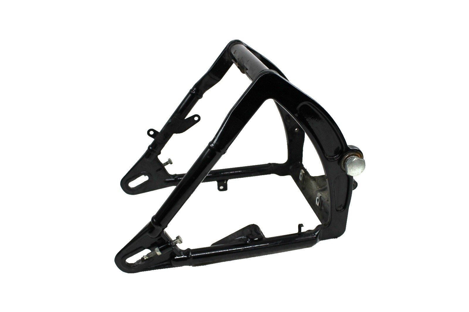
Softail transmissions do not simply "unbolt and drop." The swingarm's pivot shaft passes through the rear of the transmission case — the case is literally a structural link between the two sides of the swingarm. That means the order of battle is fixed: rear wheel out, belt freed, shocks unloaded, pivot shaft out, swingarm off, and only then does the transmission case unbolt from the frame and slide out. The engine is already out (Section 5), which gives you the room to do all of this comfortably. If you ever do this job with the engine staying in, the primary strip in Section 5 Phase C still has to happen first, because the inner primary ties the two units together.
Phase A — Right side: cables, covers, and small stuff
Clutch cable at the transmission: with the cable fully slackened at the adjuster, remove the transmission side (release) cover bolts and lift the cover. Unhook the cable from the release mechanism (note the coupling/ramp arrangement and the order of small parts — photograph it) and free the cable from the case.
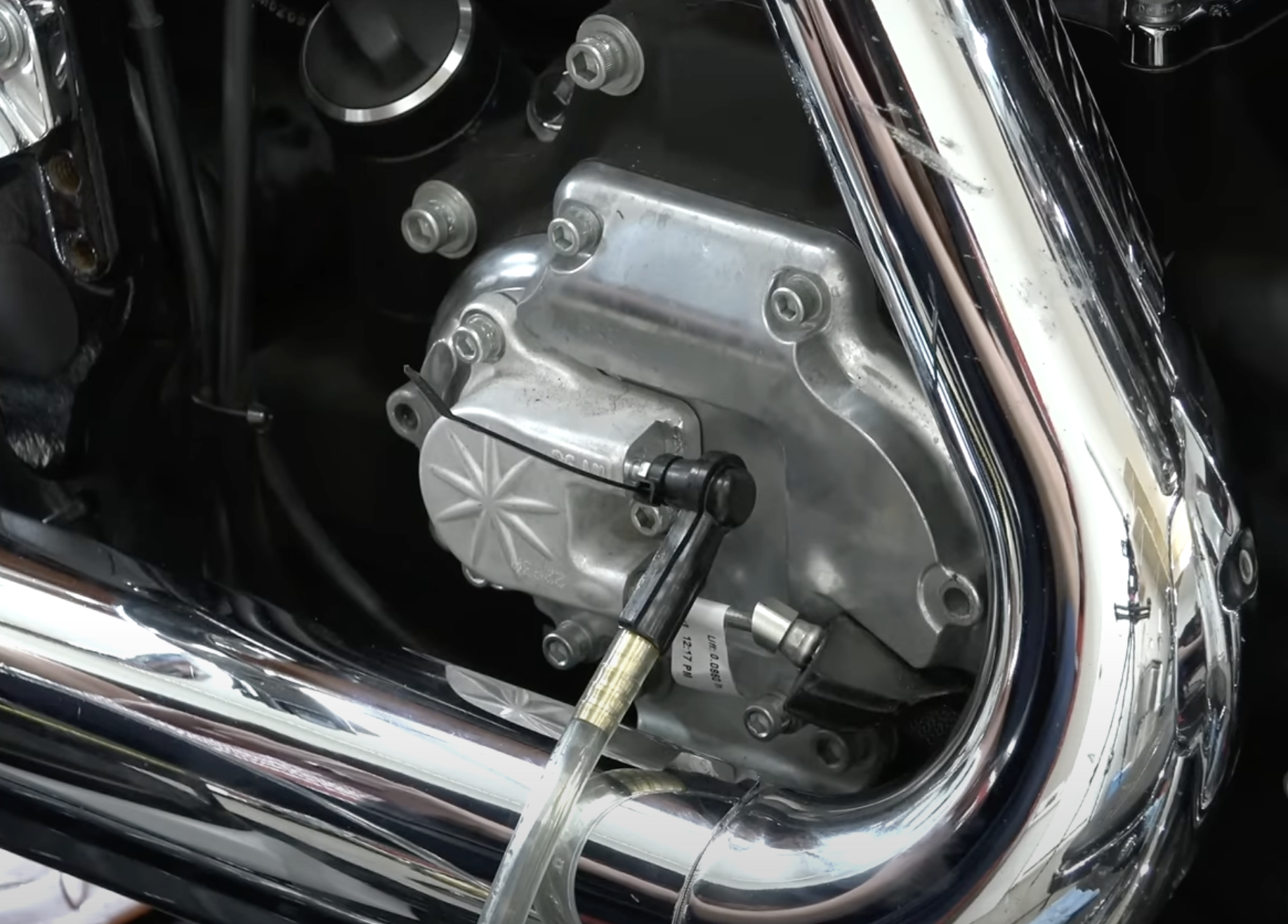
Figure 10. The transmission side (release) cover on the right side of the bike, with the clutch cable coming in from below behind the exhaust. This cover comes off to disconnect the clutch cable, and the whole area is why the exhaust had to come off first.
Speedometer sensor: unbolt it from the top of the transmission case and disconnect its plug; tie the harness clear.
Neutral switch wire off (top of the case, if not already done in Section 5).
Transmission vent hose off its fitting; cap the fitting so nothing falls in.
Shifter shaft lever: if not already marked and removed, paint-pen the spline position now, then take the linkage and lever off.
Oil tank: if it hasn't come out yet, now. Unbolt it, cap its fittings, and lift it clear — the starter and the top of the transmission case both breathe easier with it gone.
Phase B — Rear wheel and belt
Support the rear of the bike so the rear wheel can come off the ground. Mark the axle adjuster positions (count exposed threads or measure), so belt alignment goes back where it was.
Remove the rear brake caliper from its bracket (tie it up — never let a caliper hang by its hose) and free the brake stay as equipped.
Pull the axle: nut off, axle driven/slid out with a soft drift, capturing spacers in left/right order on a labeled rod or wire.
Roll the wheel forward to slack the belt, slip the belt off the rear pulley, and remove the wheel. Set it aside on its side, rotor protected.
Free the belt from the transmission output sprocket area as far as it will go — the belt is an endless loop and it fully releases only when the swingarm comes off. Keep it clean and untwisted; belts hate being folded or stepped on.
Phase C — Shocks and the swingarm pivot
The Softail's two rear shocks live under the transmission, running between the frame and the front of the swingarm. Support the swingarm with the scissor jack, then unbolt the shocks at their front (frame) ends — or at the swingarm ends — so the swingarm can move without the shocks fighting you. Note shim and spacer order.
Take the transmission's weight on the jack under the case. Nothing in the next steps should be hanging off the pivot shaft.
EXPECT THE PIVOT TO FIGHT YOU: Swingarm pivot shafts are famous for corroding into the transmission case — many were installed at the factory with little or no anti-seize, and two decades of weather welds them in place. Start soaking the pivot area with penetrating oil a day ahead if you can. Work the shaft out with a brass or soft drift and patience, never with a steel sledge swung in anger: you are driving a shaft out of an aluminum case, and the case is the expensive part.
Remove the pivot shaft end hardware on both sides (nuts/bolts and the pivot plates as equipped), keeping left and right stacks separate and in order.
Drive the pivot shaft out sideways with the drift, supporting the swingarm as it releases. If it starts to move and then binds, stop, soak, tap it back a quarter inch to break the corrosion ring, and work it back and forth rather than forcing a single pass.
Slide the swingarm rearward and off the bike, threading the belt off the transmission sprocket as the arm comes away. Lay the arm on cardboard; the belt can come fully off now.
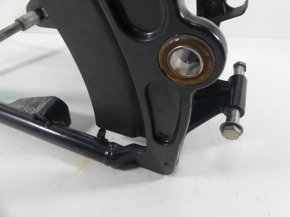
Figure 11. A Softail swingarm off the bike. The wide front cross-tube is the pivot housing — the shaft that runs through it also runs through the transmission case, which is why the arm and the gearbox come apart in the order this section describes.Figure 12. Close-up of a swingarm pivot bearing bore. Clean and inspect these bores and bearings while the arm is out — slop here becomes a weave at highway speed, and you will never have easier access than right now. On reassembly the shaft gets anti-seize so the next man (probably you) isn't fighting your corrosion.
Phase D — The case comes out
Final check around the transmission case: clutch cable off, sensor off, neutral wire off, vent capped, shift lever off, starter out, oil tank out, nothing left connected but the mounting hardware.
Jack snug under the case, taking its weight.
Remove the transmission mounting bolts (the case bolts to its mounting plate and the frame crossmember below — these are the bolts that have been hiding under the bike, around the seized drain plug's neighborhood, the whole time).
Slide the case rearward and down, then out to the right side, guiding it past the frame rails. It's an awkward 60 lb — two people, or one person and the jack walked down in stages.
Set the case on the bench on wood blocks, drain plug up-facing-your-wrench at last. This is the moment the whole project was for.
SECTION 7 On the Bench: The Plug, The Threads, The Rebuild
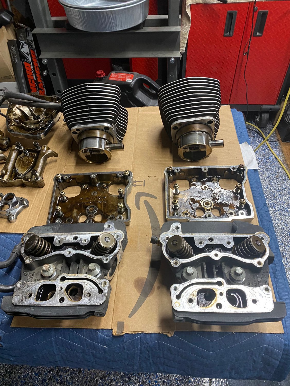
Figure 13. A Twin Cam top end laid out on the bench mid-rebuild — heads, cylinders, and rocker boxes in matched pairs. This is what "organized" looks like: every part with its partner, every fastener with its part, nothing on the floor.
7.1 Finish the plug fight — with home-field advantage
Everything from Section 3 still applies, but the bench changes the odds completely: the case is steady, the plug faces you, the drill press is square to the work, and light is no longer a flashlight in your teeth. Run the ladder again from the top — you will be surprised how often Rung 2 or 3, which failed under the bike, works at the bench simply because the socket finally sits perfectly square. Weld-a-nut (Rung 6) and the left-hand drill (Rung 7) are the closers here, and on the bench they essentially never lose.
Mount the case steady (bench vise with soft jaws on a mounting boss, or blocked solid on the bench). Never clamp sealing surfaces.
Repeat: clean, soak, shock, six-point socket (Rungs 1–2), then heat-and-freeze (Rung 3), then impact driver (Rung 4), then extractor socket (Rung 5).
Weld-a-nut (Rung 6) if the head is gone. On the bench this is a five-minute job and it is the single most reliable extraction in this whole guide.
Left-hand drill (Rung 7) as the last resort, on the drill press, with the case fixtured so the bit is dead square to the plug. Grease the bit; stop and clear chips often.
The plug is out. Now clean the hole like you mean it: brake cleaner, a small brush, and a bright light. What remains in that hole decides which repair you need.
7.2 Judge the threads — and repair them honestly
What you find
The fix
Notes
Threads clean and whole — the plug was simply rusted in place.
Chase the threads lightly with a 1/2-20 thread chaser (a chaser cleans; a tap cuts). Flush the hole. Done.
This is the usual outcome when the corrosion was in the plug threads rather than the case threads. New plug, new O-ring, correct torque.
Threads galled or partly torn — a new plug wobbles or won't start square.
Time-Sert solid threaded insert (1/2-20 kit). Drill, tap, and install the solid steel insert per the kit instructions.
The gold-standard repair: a solid insert is stronger than the original aluminum threads and seals exactly like stock. Preferred over wire-coil inserts (Helicoil) in an oil drain, because there is no loose coil tail to worry about and the insert is a permanent, full-strength thread.
Threads badly damaged, case thin, or you're mid-trip
Oversize self-tapping drain plug (sold in single- and double-oversize for 1/2-20 holes). It cuts its own slightly larger thread as it goes in.
A legitimate get-you-home and often a permanent fix, but treat it as second choice behind Time-Sert: it leaves a non-standard thread, and the next plug must match it. Mark the case with a paint pen: "OS PLUG" so nobody forces a stock plug in later.
Hole cracked or boss broken
Machine shop: weld up the boss and re-machine the thread, or replace the pan/case section.
Rare, and usually the result of gorilla torque during someone's earlier "fix." A good welder who knows cast aluminum is worth every penny here.
CHEAP INSURANCE, EVERY TIME: Throw the old plug in the scrap bin no matter how it looks, and install a new magnetic drain plug with a fresh O-ring. The magnet catches the fine metal fuzz that tells you what's wearing inside, the new O-ring actually seals, and the whole thing costs less than the oil you're about to pour in. On installation: start it by hand until it seats (a cross-threaded start is how Section 7.2 happens), then torque to 14–21 ft-lb. That number feels light. It is correct anyway — the O-ring does the sealing, not brute force. The reason this plug was seized in the first place is very likely that somebody before you "made sure" it was tight.
7.3 Reassembly — the whole job in reverse, with torque
Reassembly is disassembly backwards, with three upgrades: everything goes back clean, critical threads get the threadlocker named in the table, and every fastener that matters gets a torque wrench, not a calibrated elbow. Order:
Transmission in: case onto its mounts with the jack, mounting bolts in, drain plug verified (new plug, new O-ring, 14–21 ft-lb) before the case goes back under the bike — last easy chance.
Swingarm and pivot: belt looped over the transmission sprocket first, swingarm threaded into place, pivot shaft in with anti-seize on the shaft, pivot hardware torqued. Shocks reconnected.
Rear wheel: axle in with spacers in their labeled order, caliper back on, belt aligned and tensioned (about 3/8–1/2 in deflection with 10 lb of upward force at the midpoint, checked with the wheel off the ground — confirm against the factory spec for your model), axle nut torqued, adjusters locked evenly.
Engine in: reverse of Section 5 Phase D — in from the right, forward off nothing, onto the dowels, mounts in finger-tight first, then torqued: front mount bolts, engine-to-transmission bolts (two steps: snug all to 15 ft-lb, then 30–35 ft-lb), top mount last.
Starter and inner primary: starter bolted up, jackshaft in; inner primary over the shafts with fresh seals, bolts torqued to 18–21 ft-lb with blue threadlocker.
Primary drive: compensator, chain, and clutch back on as the one loop they came off as. Locking tool in. Clutch hub nut: LEFT-HAND — it tightens counterclockwise, red threadlocker, 70–80 ft-lb. Compensator nut: right-hand, red threadlocker, 150–165 ft-lb. Adjust primary chain free play (5/8–7/8 in total up-and-down at the tightest spot, cold) and button up the outer primary with a new gasket; cover bolts 84–108 in-lb in a crisscross pattern.
Everything reconnected from your tags and photos: oil lines (feed and return on the fittings you labeled — double-check against the photos), all wiring connectors, coil and plug wires, clutch cable and adjustment, shift linkage on its paint-pen mark, throttle cables.
Tank, exhaust, seat: exhaust with new port gaskets, flange nuts snugged evenly; tank on, fuel line connected; battery in — positive first this time, negative last.
7.4 Torque table — 2002 Softail, Twin Cam 88B
Values below are the commonly cited factory specifications for this model, gathered from multiple published references. Where references disagreed, the factory service manual's range is the one shown. Verify any fastener marked * against the factory manual (H-D P/N 99482-02) before final assembly — see the note at the end of this guide.
Fastener
Torque
Notes
Engine oil drain plug
14–21 ft-lb
New O-ring every time. No tape, no sealant.
Transmission drain plug
14–21 ft-lb
New O-ring. The star of this guide.
Primary drain plug (T-40)
14–21 ft-lb
Pipe thread; a little sealant is OK. Threads strip easily — err low.
Compensator nut
150–165 ft-lb
Right-hand thread. Red Loctite 262/271. Locking tool required.
Clutch hub nut
70–80 ft-lb
LEFT-HAND THREAD — tightens counterclockwise. Red Loctite.
Inner primary to engine/transmission
18–21 ft-lb
Blue Loctite 243.
Outer primary cover bolts
84–108 in-lb
Crisscross pattern, new gasket.
Derby (clutch inspection) cover bolts
84–108 in-lb
Crisscross; the cover warps if you lean on it.
Transmission side cover bolts
84–108 in-lb
Even, crisscross.
Engine-to-transmission bolts
30–35 ft-lb
Two-step: 15 ft-lb first pass, then final.
Front engine mount bolts
33–38 ft-lb
Solid-mount engine — no isolators to crush.
Top engine mount (to heads)
18–21 ft-lb
Blue Loctite 243.
Transmission sprocket (output pulley) nut *
100–110 ft-lb
Red Loctite; hold the sprocket properly, not with the belt.
Swingarm pivot shaft nut *
80–90 ft-lb
Anti-seize on the shaft before it goes in.
Rear shock mounting bolts *
55–65 ft-lb
Both sides even.
Rear axle nut *
95–105 ft-lb
After belt alignment is set and verified.
Transmission top cover bolts
84–108 in-lb
—
Oil filter
Hand-tight + 1/2 to 3/4 turn
Oil the gasket; never a wrench-tightened filter.
SECTION 8 Fluids, Adjustments & First Start
Fill it up
Primary: 32 oz (1 quart) of primary fluid through the derby cover opening, bike upright, until the fluid reaches the bottom edge of the clutch diaphragm spring. Derby cover on, bolts at 84–108 in-lb.
Transmission: 20–24 oz of transmission oil through the filler/dipstick plug on the side cover. Check the level on the dipstick per the marks.
Engine: new filter on (gasket oiled, hand-tight plus a half to three-quarter turn). Pour 2.5 quarts of 20W-50 into the oil tank. Leave the last half quart on the bench for topping up after the first run — the tank lies to you until the oil has circulated and the filter has filled.
Clutch adjustment: at the cable adjuster and at the release mechanism — set cable free play at the lever to a coin's thickness (about 1/16–1/8 in) and confirm the clutch disengages cleanly.
Belt: recheck deflection and alignment after the first short ride and re-torque check on the axle nut.
First start checklist
All three drain plugs torqued and dry to the touch
Oil tank at 2.5 qt, filler cap on
Battery terminals tight, cables routed clear of the seat pan
Fuel on / fuel line connected, no leaks at any fitting — sniff test, then eyes
Transmission in neutral, neutral light on, bike strapped or on its sidestand as you prefer, clutch in for the start
Start it. Watch the oil pressure light: it must go out within a few seconds. If it doesn't, kill it and find out why before running it again
Idle two minutes while you walk around it with a flashlight: every drain plug, the primary seam, the inner primary seals, oil line fittings, exhaust flanges
Shut down, wait two minutes, check engine oil on the dipstick (bike on the sidestand) and top up toward full in small sips
Short, gentle first ride. Re-check every fluid level and every plug when it's back, hot
At 50 miles: re-check drain plugs, axle nut, belt, and the compensator's world in general. At 500: change the engine oil and filter again — a fresh rebuild sheds its break-in debris into the first oil, and cheap oil changes are cheaper than engines
LAST WORD: The plug that started all of this will never seize again if it goes in with a fresh O-ring, clean threads, and 14–21 ft-lb — and if it comes out once a year for an oil change instead of once a decade. Write the date of this rebuild on the inside of the side cover with a paint pen. Lou & Buck were here, and they did it themselves.
Figure sources
Reference photographs and drawings used in this guide, retrieved October 2026. All text is original to this guide; figures are reproduced for identification and instruction.
Figure 1 — Softail on a garage jack: hdforums.com, Softail Standard picture thread (www.hdforums.com/forum/softail-pictures/16144-softail-standard-pictures-163.html)
Figure 2 — Twin Cam 88 studio view: J&P Cycles, "Harley-Davidson Engines Through History" (www.jpcycles.com/common-tread/harley-engine-history)
Figure 4 — Underside drain plug graphic: Harley-Davidson Service Information Portal graphic 1833987 (serviceinfo.harley-davidson.com)
Figure 5 — Bottom pan line drawing: Harley-Davidson Service Information Portal graphic sm02174 (serviceinfo.harley-davidson.com)
Figure 13 — Twin Cam top end on the bench: hdforums.com, "Can we save this 88?" thread (www.hdforums.com/forum/twin-cam-motors/1486326-can-we-save-this-88-a.html)
Figure 3 is an original schematic drawn for this guide.
Disclaimer: This is a garage guide written by enthusiasts, not the factory service manual, and not a substitute for one. Torque values and procedures here reflect commonly published references for the 2002 Softail Twin Cam 88 and were reconciled across several sources, but the factory manual — 2002 Harley-Davidson Softail Service Manual, H-D P/N 99482-02 — is the final word on every specification. If this guide and the factory manual ever disagree, the factory manual wins. Work safe, and when in doubt, stop and check.